Refractory plastic is a material composed of refractory aggregates of a defined particle size distribution, powders, binders, and admixtures, which are then mixed, kneaded, and extruded into blocks or lumps. This amorphous refractory material retains excellent plasticity after a period of packaging and storage, allowing it to be applied by ramming.
Refractory plastic offers advantages such as high-temperature strength, excellent thermal shock resistance, low thermal conductivity, strong resistance to spalling and slag erosion, long service life, and energy conservation. It is particularly suitable for easily damaged and difficult-to-form areas such as furnace roofs and burner bricks. It is primarily used in the steel industry for linings of various heating furnaces, soaking pits, annealing furnaces, sintering furnaces, and electric furnace roofs.
Construction Characteristics of Refractory Plastics in the Furnace Roof
Refractory plastics are air-hardening or thermosetting materials. Due to their low water content, plastics harden quickly upon exposure to air. Therefore, the joint surface must be continuously constructed during plastic refractory installation. Plastic blocks must be held together by a certain external force, which must be perpendicular to the construction surface.
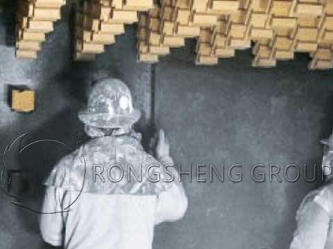
When plastics are used in the furnace roof, due to the suspended structure of the furnace roof, anchor bricks are used to hold the refractory material together as a single unit. This requires a tight bond between the plastic and the anchor bricks. The anchor bricks are suspended from the steel structure of the furnace roof. During plastic refractory installation, each anchor brick must be prestressed to ensure uniform stress distribution across the furnace roof and prevent collapse. When plastics are subjected to external forces, they inevitably expand in all directions, making it difficult to maintain the required thickness of the furnace roof. This requires the installation of formwork on both the upper and lower surfaces of the furnace roof to control the plastic thickness within the required range.
Plastics shrink at high temperatures, eliminating the need for traditional expansion joints. However, to prevent irregular cracks from shrinking, slitting can be used during construction.
The surface of the processed plastic is smooth, which is not conducive to bonding. Therefore, the joint surface should be as rough as possible. After construction, the outer surface should also be roughened, with some air holes punched to facilitate the removal of moisture from the plastic.
Construction Preparation
Based on the plastic refractory installation process requirements for refractory plastics, prepare an air compressor (or a stable air source with a pressure of 0.7 MPa), an air hammer, wooden formwork bricks, scraping tools, expansion joint cutting tools, air venting tools, tools for drawing and forming, wooden and steel formwork, etc.
The production of wooden formwork bricks is crucial; they must be made in a 1:1 ratio with the actual anchor bricks. Two types of wooden formwork bricks are required for the furnace roof: One surface perpendicular to the centerline of the furnace (when the anchor brick is hung on the furnace roof) does not require a groove and can be planed flat. The remaining five surfaces are machined to the actual dimensions of the anchor brick, and one-fifth of the actual brick quantity is required. The other surface parallel to the centerline of the furnace (when the anchor brick is hung on the furnace roof) does not require a groove and can be planed flat. The remaining five surfaces are machined to the actual dimensions of the anchor brick, and ten bricks are sufficient.
The Construction of the Refractory Plastics in the Furnace Roof
The preloading and formwork construction techniques ensure that the stresses on the furnace steel structure after formwork removal are essentially the same as before, preventing significant deflection changes in the steel structure after formwork removal, which could lead to uneven stress on the furnace lining and even fracture. During furnace roof construction, preloading and formwork construction ensure that the deformation of the furnace roof steel structure is roughly synchronized with that of the furnace lining. Otherwise, fracture or roof collapse could occur after heating.
The furnace roof formwork is constructed using special screws with threads on both ends, which are adjusted using nuts at both ends.
The furnace roof utilizes a suspended formwork. The installation elevation of the formwork should be approximately 5 mm lower than the designed furnace roof height to maintain adequate roughening and correction allowances on the interior surface. The vertical spacing of the hanging screws is 1.0-1.5 m, and the horizontal spacing is: formwork length + formwork bolt diameter + (5-10) mm. The formwork is laid horizontally on a suspended 40 mm scaffolding tube, while the wooden upper formwork is laid simultaneously. The upper and lower formwork are laid in sections as the plastic is rammed, and the wooden upper formwork is recycled. Once the entire furnace roof is constructed, the formwork is removed together. Immediately after removal, the roughening is shaved, the brick surfaces are trimmed, expansion joints are cut, and ventilation holes are drilled. Adjust the nuts to ensure a 5 mm gap between the suspended anchor bricks and the lower formwork. The press-down area should be drawn starting from the lowest horizontal section, then sloped toward both ends, finally transitioning to the horizontal section at the furnace roof. The draw at the “door closing” area will depend on the site conditions.
The specific construction process for the heating furnace roof is as follows:
1) Ramming the roof is generally carried out in sections. The force applied by the ramming hammer should be perpendicular to the working surface of the roof to prevent spalling of the working surface due to poor bonding between the materials, thereby increasing the lifespan of the roof.
2) Only a single layer of plastic material (50 mm thick) should be laid per layer. The pneumatic hammer should be perpendicular to the ramming surface, and ramming should begin at the joint of the blank. The hammer should move vertically between the upper and lower formworks, with the hammer marks overlapping by 2/3 and the rows overlapping by 1/2. Ramming should be repeated at least once. After tamping, the surface should be flat, dense, and uniform.
3) Plastic material should be applied continuously. During breaks, cut the material perpendicular to the furnace shell at right angles and cover with plastic sheeting to prevent moisture loss. If construction is interrupted for an extended period, the joint should remain at the centerline of the two rows of anchor bricks. When resuming construction, cut and shave the dried surface.
4) Before installing anchor bricks or hanging bricks, wedge and hammer the plastic material with wooden form bricks of the same tooth shape. After the tooth marks are formed, insert the anchor bricks and wedge them in place. The hanging bricks must be wedged tightly against the hanging beams. The contact between the furnace roof hanging anchor bricks, hanging steel bar rings, and hanging steel pipes must be tightly tensioned and under load to prevent the furnace roof from sinking when the formwork is removed.
5) The furnace roof “door” should be located in a location with minimal obstructions in the horizontal furnace roof section. The width of the “door” should not exceed 600 mm. The “door” should be rammed into a funnel shape and kept as small as possible. The material should be laid and rammed layer by layer.
6) After the plastic material is applied, the formwork should be removed as soon as possible to allow moisture in the lining to dissipate. Before making any corrections, gently tap the plastic material around the end of the anchor brick with a wooden hammer or ramming hammer to ensure a tight fit. Then, remove any excess material using the end of the anchor brick or hanging brick as a reference. Corrections include scraping, drilling ventilation holes, and cutting expansion joints.
7) After removing the formwork, use a spiked brush or scraping hoe to scrape the surface of the construction. This facilitates moisture removal and prevents cracks.
8) Use a small, pointed chisel with a diameter of 2-3 mm to drill ventilation holes in the heated surface of the plastic lining. The depth should be 2/3 of the lining thickness, but no more than 200 mm, and the spacing should be 150 mm.
9) Expansion joints on the heated surface of the plastic lining should be cut according to the designed location, with a depth of 50-80 mm and a spacing of 1.2-1.8 m. A rigid blade should be used to cut the expansion joints; the thinner the better.
Precautions
1) plastic refractory installation must not come into contact with water during or after construction.
2) When applying castables in contact with plastic construction, ensure that the plastic refractory installation is waterproof.
3) Before kiln curing, remove the formwork as soon as possible to allow the masonry to dry naturally.
4) Due to the “zero expansion” design of plastic, cracks and widening expansion joints are normal in plastic masonry during drying and kiln curing. However, if cracks exceed 10 mm in width, fill the cracks and expansion joints with refractory fiber to prevent flames and smoke from the furnace lining at low temperatures. Cracks and expansion joints tend to close at around 1,350°C.
5) Plastic products generally measure 230 mm × 185 mm × 50 mm. Six pieces are sealed in plastic bags. They should be stored indoors, out of direct sunlight and away from high temperatures. Waterproof and frost-proof, and unpacked only when ready for use. The ambient temperature during construction should be above 5°C.
6) Plastic is a gas-hardening or heat-hardening refractory material. The temperature should be raised to 1,300°C at a rate of 50°C/h⁻¹ and held at that temperature for 24 hours before lightweight castables for the furnace roof can be applied. Otherwise, the plastic must be properly waterproofed.
Performance
1) A steel group imported refractory plastic for the roofs of three French Stein digital heating furnaces. After two years of operation, the results have been excellent.
2) Due to the plastic’s “zero expansion” design, previous problems with furnace roof burn-through and fire penetration have been virtually eliminated.
3) Due to the plastic’s low moisture content, no water is added during the entire plastic refractory installation process, shortening the furnace drying time and significantly reducing the risk of cracking in the furnace roof due to inadequate moisture removal.